PROMO DISKON
Tidak ada produk yang dapat ditampilkan
BARU RILIS

Pompa Bilge DC 12V &..
Rp 180,000

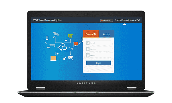
Pemancar arus listri..
Rp 2,515,000

Pompa Booster 90 Wat..
Rp 289,000

Pemancar Arus Pagar ..
Rp 1,330,000

Kunci Roda Impact wr..
Rp 390,000

Mata Bor Countersink..
Rp 70,000

Screw Extractor pemb..
Rp 15,000

Mesin bor beton Impa..
Rp 183,000

Pompa Minyak DC 24V ..
Rp 270,000

Pelampung Toren Otom..
Rp 33,500

Pompa Celup Solar DC..
Rp 55,000

Pompa Celup Solar DC..
Rp 55,000

Lampu Sorot Baterai ..
Rp 150,000

Gulungan Selang Air ..
Rp 345,000

Pagar Listrik 5 Joul..
Rp 2,100,000

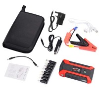
Jump Starter Powerba..
Rp 523,000

Lampu Sorot LED Sent..
Rp 89,000

Anti Petir pagar lis..
Rp 225,000

Pompa Minyak DC 12V ..
Rp 270,000
-300x300.png)
-4%
Adaptor Lighter DC 1..
Rp 65,000
Rp 68,000


PENJUALAN TERBAIK
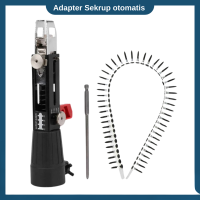
Adapter Sekrup otoma..
Rp 95,000
-200x200.png)
-4%
Adaptor Lighter DC 1..
Rp 65,000
Rp 68,000
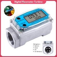
Alat Ukur Debit Cair..
Rp 245,000
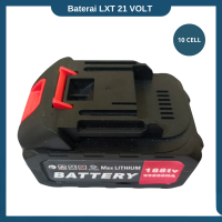
Baterai Gergaji Rec..
Rp 90,000
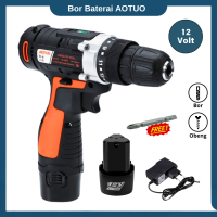
Bor baterai 12 Volt ..
Rp 220,000
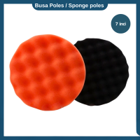
Busa Mesin Poles 7 I..
Rp 40,000
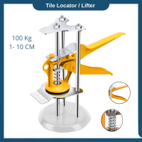
Dongkrak Pengatur ke..
Rp 38,500
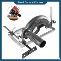
Dudukan Gerinda Circ..
Rp 72,000
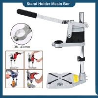
Dudukan mesin bor st..
Rp 158,000
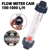
Flowmeter Air Rotame..
Rp 100,000
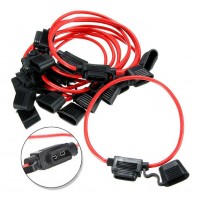
Fuse Holder Waterpro..
Rp 8,000
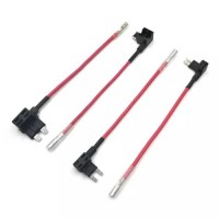
Fuse Tap Kabel Jumpe..
Rp 8,900
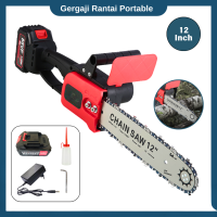
Gergaji rantai 12 in..
Rp 495,000
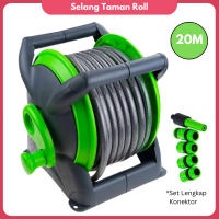
Gulungan Selang Air ..
Rp 345,000
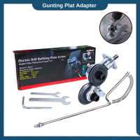
Gunting plat besi ad..
Rp 55,000

Hedge trimmer Mini 2..
Rp 270,000
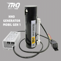
HHO Generator TRQ Mo..
Rp 1,020,000
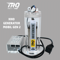
HHO Generator TRQ Mo..
Rp 1,250,000
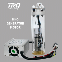
HHO Generator TRQ Mo..
Rp 485,000
Jump Starter Powerba..
Rp 523,000
-
Transaksi Langsung
Customer Terhubung Langsung Ke Penjual Dan Distributor Via Chat Whatsapp
-
Seller Support
Online 24/7 via Whatsapp dan dapat dihubungi dimasing-masing halaman produk
-
Transaksi Aman
Pembayaran 100% Melalui Rekening Bersama (Escrow) Hingga Transaksi Selesai
-
Komisi Afiliasi
Dapatkan Komisi Setiap Kali Member Downline Anda Bertransaksi, Selengkapnya...